|
ERROR!
You must enable Java Script on your browser to navigate this site. |
||||||||||||||
|
Isolated Stackable DAQ
|
 |
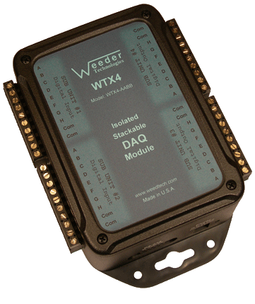
Isolated DAQ Module WTX4 Up to 32 high current open collector outputs which can directly drive relays, solenoids, DC motors, or other equipment of up to 1.0 Amp each. Can also include a combination of other I/O types. read more... |
 |
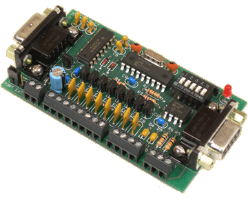
Digital Output Card 8 high current open collector outputs can directly drive relays, solenoids, DC motors, or other equipment of up to 1.0 Amp each. Also includes 2 digital input channels. read more... |
 |
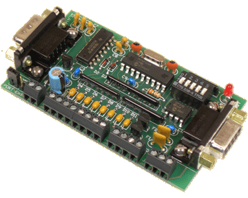
Digital Input Card 2 high current open collector outputs can directly drive relays, solenoids, DC motors, or other equipment of up to 1.0 Amp each. Also includes 8 digital input channels. read more... |
 |
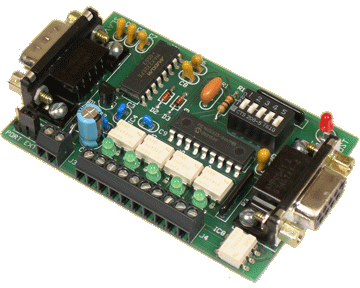
Solid State Relay Card 5 optically isolated solid state relays can be wired directly to in-circuit buttons and switches to allow software control of their operation. Built-in sequence generator. read more... |
 |
Relay Controller Card Used as the host to the Solid State Relay Module. Switches wired to it's inputs will control the on/off states of the WTSSR relays via a remote data link. read more... |
Stackable Capability
Stackable refers to the ability to connect multiple units together and share a single communications port of a host PC, laptop, or Single Board Computer (SBC). The DAQ modules are offered in two different footprints as shown above, enclosed in a case with full electrical isolation, or a
Host Communications
To communicate with the DAQ modules, commands are sent to the individual units by including a header character at the beginning (the address) so that it can be routed to the appropriate unit. If using multiple units connected together, the DIP switch for each unit should be set to a different position so that it will be assigned a different header character. Each DAQ module has its own command set used to configure it, operate the functions, and to read data from it. These commands are listed in the product data sheets. A typical command string looks like this:
HCNV{cr}
H = Header Character
C = Command Character
N = Channel Number (if applicable)
V = Value (if applicable)
{cr} = Carriage Return
If using our ModCom HMI software, the carriage return is not necessary because ModCom automatically inserts this at the end of each command string. ModCom has a communications dialog box which can be used to transmit individual commands to the DAQ modules and see the data coming back. This is helpful in learning the style of the
Output Current
The output channels of the WTX4, WTDOT-M, and WTDIN-M series uses an open-collector configuration which can sink up to 1.0 amps per channel allowing them to directly drive relays, solenoids, DC motors, magnetic latches, flow valves, etc. To attach the outputs to a device such as a relay or solenoid, connect one side of the coil to the positive side of an appropriate power source, the other side of the coil to one of the output channels of the Digital Output module, and the COM or GND terminal of the Digital Output module to the negative side (or ground) of the power source. Then use the LOW command to pull the output channel to ground which will complete the circuit and current will flow through the coil activating the relay or solenoid. The HIGH command can be used to release the output channel from ground and deactivate the relay or solenoid.
Output Timer Function
Each of the output channels of the Digital Output modules incorporate its own independentThis same procedure can be used to turn on an external alarm or warning light if there are any communications problems by having the host continuously transmitting a deactivation command instead of the activation command mentioned above. When using this method, the DEFAULT command should be used to make sure the output channel is set to the deactivation state upon power up.
PWM Output Function
The WTX4, WTDOT-M, and WTDIN-M series incorporate a special function that will produce a PWM (Pulse Width Modulation) output using the PWM command. In this mode, the output is a continuous square wave with a variable duty cycle which is controlled by the host. Duty Cycle represents the percentage of high time to low time of each pulse and can be used to control the current flow through a load such as a DC motor or flow control valve, for instance. The duty cycle can be adjusted in 0.1% increments from 0 to 1000.
Output Overload Shutdown
Each of the output channels of the WTX4, WTDOT-M, and WTDIN-M series incorporate a resettable fuse which protects it from excessive current flow. If the current being sunk by an output channel exceeds 1.0 amps for an extended period of time, the output will automatically shut down to prevent damage to the output drivers. Once this happens, the current must be removed from the output channel before it will return to normal operation.
